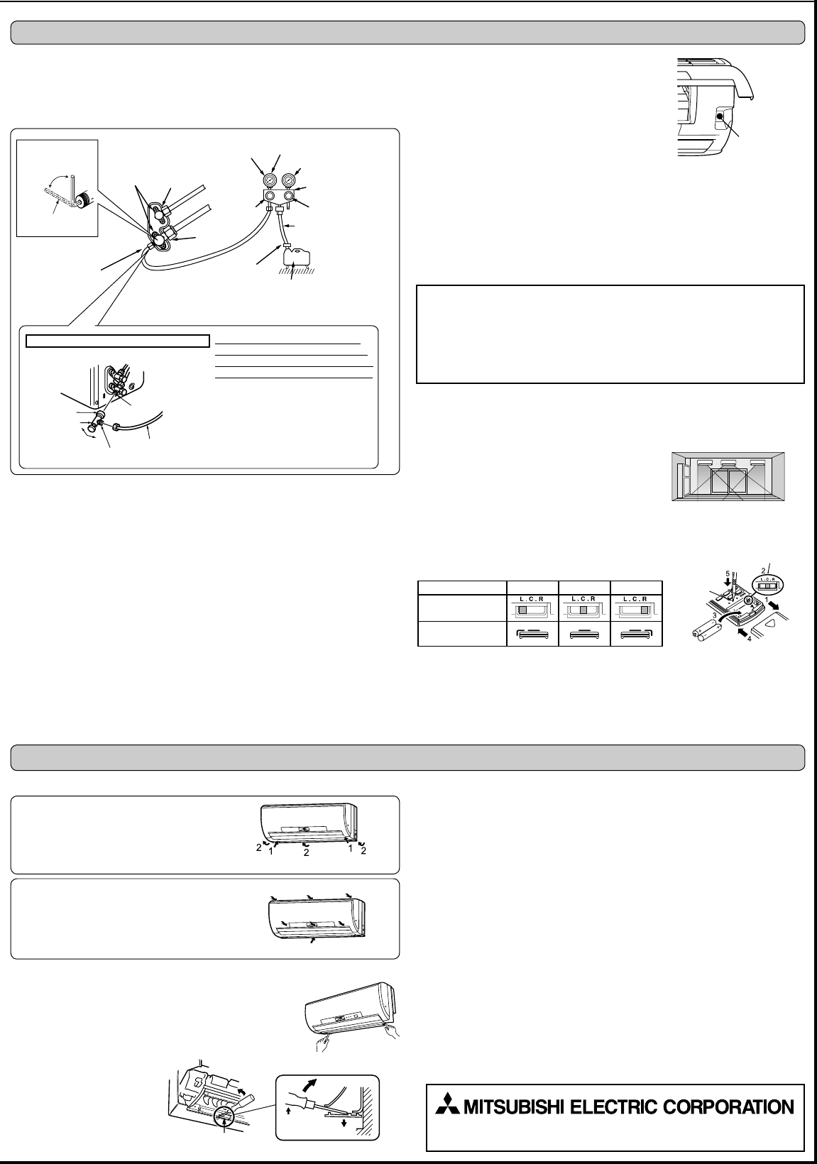
4-1. PURGING PROCEDURES AND LEAK TEST
1) Remove service port cap of stop valve on the side of the outdoor unit gas pipe. (The
VWRSYDOYHZLOOQRWZRUNLQLWVLQLWLDOVWDWHIUHVKRXWRIWKHIDFWRU\WRWDOO\FORVHGZLWKFDS
on.)
2) Connect gauge manifold valve and vacuum pump to service port of stop valve on the
gas pipe side of the outdoor unit.
5-1. REMOVING AND INSTALLING THE PANEL ASSEMBLY
5-3. PUMPING DOWN
:KHQUHORFDWLQJRUGLVSRVLQJRIWKHDLUFRQGLWLRQHUSXPSGRZQWKHV\VWHPIROORZLQJWKH
procedure below so that no refrigerant is released into the atmosphere.
1) Connect the gauge manifold valve to the service port of the stop valve on the gas pipe
side of the outdoor unit.
)XOO\FORVHWKHVWRSYDOYHRQWKHOLTXLGSLSHVLGHRIWKHRXWGRRUXQLW
&ORVHWKHVWRSYDOYHRQWKHJDVSLSHVLGHRIWKHRXWGRRUXQLWDOPRVWFRPSOHWHO\VRWKDW
LW FDQ EH HDVLO\ FORVHG IXOO\ ZKHQ WKH SUHVVXUH JDXJH VKRZV 03D >*DXJH@ NJI
cm
2
).
6WDUWWKHHPHUJHQF\&22/RSHUDWLRQ
To start the HPHUJHQF\RSHUDWLRQ LQ &22/ PRGHGLVFRQQHFW WKH SRZHU VXSSO\ SOXJ
DQGRU WXUQ RII WKH EUHDNHU $IWHU VHFRQGV FRQQHFW WKH SRZHU VXSSO\ SOXJ DQGRU
turn on the breaker, and then press the E.O. SW once. (The HPHUJHQF\&22/
operationFDQEHSHUIRUPHGFRQWLQXRXVO\IRUXSWRPLQXWHV
)XOO\FORVHWKHVWRSYDOYHRQWKHJDVSLSHVLGHRIWKHRXWGRRUXQLWZKHQWKHSUHVVXUH
JDXJHVKRZVWR03D>*DXJH@DSSUR[WRNJIFP
2
).
6) Stop the HPHUJHQF\&22/RSHUDWLRQ
.
Press the E.O. SW twice to stop the operation.
5-2. REMOVING THE INDOOR UNIT
Remove the bottom of the indoor unit from the installation plate.
When releasing the corner part, release both left and right bottom
corner part of indoor unit and pull it downward and forward as
VKRZQLQWKH¿JXUHRQWKHULJKW
If the above method cannot be used
5HPRYHWKHIURQWSDQHO7KHQLQVHUWKH[DJRQDOZUHQFKHVLQWRWKH
square holes on the left and right
sides of the unit and push them
XSDVVKRZQLQWKHIROORZLQJ¿J
-
ure. The bottom of the indoor unit
lowers and releases the hooks.
Removal procedure
5HPRYHWKHVFUHZVZKLFK¿[WKHSDQHODVVHP
-
EO\
5HPRYH WKH SDQHO DVVHPEO\ %H VXUH WR UHPRYH
LWVERWWRPHQG¿UVW
Installation procedure
,QVWDOO WKH SDQHO DVVHPEO\ IROORZLQJ WKH UHPRYDO
procedure in reverse.
%HVXUHWRSUHVVWKHSRVLWLRQVDVLQGLFDWHGE\WKH
DUURZVLQRUGHUWRDWWDFKWKHDVVHPEO\FRPSOHWHO\
to the unit.
Stop valve for
GAS
Stop valve cap
(Torque 19.6 to
29.4 N•m, 200
WRNJIƒFP
Vacuum pump (or the vacuum
pump with the function to
SUHYHQWWKHEDFNÀRZ
Gauge manifold valve
(for R410A)
Compound pressure gauge
(for R410A)
–
0.101 MPa
(
–
760 mmHg)
Handle
Low
Handle High
Adapter for pre-
venting the back
ÀRZ
Charge hose
(for R410A)
*Close
*Open
+H[DJRQDOZUHQFK
Precautions when using the control valve
When attaching the control valve
WRWKHVHUYLFHSRUWYDOYHFRUHPD\
GHIRUPRUORRVHQLIH[FHVVSUHVVXUH
LVDSSOLHG7KLVPD\FDXVHJDVOHDN
Service port
Charge hose
%RG\
Close
Open
Control valve
A
When attaching the control valve to
the service port, make sure that the
valve core is in closed position, and
then tighten part A. Do not tighten
SDUW$RUWXUQWKHERG\ZKHQYDOYH
core is in open position.
Service port cap
(Torque 13.7 to
17.7 N•m, 140 to
180 kgf•cm)
*4 to 5 turns
3) Run the vacuum pump. (Vacuumize for more than 15 minutes.)
4) Check the vacuum with gauge manifold valve, then close gauge manifold valve, and
stop the vacuum pump.
5) Leave as it is for one or two minutes. Make sure pointer gauge manifold valve remains
LQWKHVDPHSRVLWLRQ&RQ¿UPWKDWSUHVVXUHJDXJHVKRZV±03D>*DXJH@±
mmHg).
5HPRYHJDXJHPDQLIROGYDOYHTXLFNO\IURPVHUYLFHSRUWRIVWRSYDOYH
$IWHUUHIULJHUDQWSLSHVDUHFRQQHFWHGDQGHYDFXDWHGIXOO\RSHQDOOVWRSYDOYHVRQERWK
VLGHVRIJDVSLSHDQGOLTXLGSLSH2SHUDWLQJZLWKRXWIXOO\RSHQLQJORZHUVWKHSHUIRUP
-
ance and this causes trouble.
8) Refer to 1-3., and charge the prescribed amount of refrigerant if needed. Be sure to
FKDUJH VORZO\ ZLWK OLTXLG UHIULJHUDQW 2WKHUZLVH FRPSRVLWLRQ RI WKH UHIULJHUDQW LQ WKH
V\VWHPPD\EHFKDQJHGDQGDIIHFWSHUIRUPDQFHRIWKHDLUFRQGLWLRQHU
9) Tighten cap of service port to obtain the initial status.
10) Leak test
4-2. TEST RUN
,QVHUWSRZHUVXSSO\ SOXJLQWRWKHSRZHURXWOHWDQGRUWXUQRQWKHEUHDNHU &KHFNWKDW
DOO/('ODPSVDUHQRWOLW,IWKH\DUHEOLQNLQJFKHFNWKDWWKHKRUL]RQWDOYDQHLVLQVWDOOHG
FRUUHFWO\5HIHUWRRSHUDWLQJLQVWUXFWLRQVIRUGHWDLOV
2) Press the E.O. SW once for
COOL, and twice for HEAT operation. Test run will be per-
IRUPHGIRUPLQXWHV,IWKHRSHUDWLRQLQGLFDWRUEOLQNVHYHU\VHFRQGVLQVSHFWWKH
LQGRRURXWGRRUXQLW FRQQHFWLQJ ZLUH $ IRUPLVZLULQJ $IWHU WKHWHVW UXQ HPHUJHQF\
Stop valve
for LIQUID
Caution:
• After test run or remote signal reception check, turn off the unit with the E.O. SW or
WKHUHPRWHFRQWUROOHUEHIRUHWXUQLQJRIIWKHSRZHUVXSSO\1RWGRLQJVRZLOOFDXVHWKH
XQLWWRVWDUWRSHUDWLRQDXWRPDWLFDOO\ZKHQSRZHUVXSSO\LVUHVXPHG
To the user
$IWHULQVWDOOLQJWKHXQLWPDNHVXUHWRH[SODLQWKHXVHUDERXWDXWRUHVWDUWIXQFWLRQ
,I DXWR UHVWDUW IXQFWLRQ LV XQQHFHVVDU\ LW FDQ EH GHDFWLYDWHG &RQVXOW WKH VHUYLFH
representative to deactivate the function. Refer to the service manual for details.
Push
Lower
Square hole
4. PURGING PROCEDURES, LEAK TEST, AND TEST RUN
Pressure gauge
(for R410A)
5. RELOCATION AND MAINTENANCE
HEAD OFFICE: TOKYO BLDG., 2-7-3, MARUNOUCHI, CHIYODA-KU, TOKYO
100-8310, JAPAN
4-5. EXPLANATION TO THE USER
8VLQJWKH23(5$7,1*,16758&7,216H[SODLQWRWKHXVHUKRZWRXVHWKHDLUFRQGL-
WLRQHUKRZWRXVHWKHUHPRWHFRQWUROOHUKRZWRUHPRYHWKHDLU¿OWHUVKRZWRUHPRYH
or put the remote controller in the remote controller holder, how to clean, precautions
for operation, etc.)
5HFRPPHQGWKHXVHUWRUHDGWKH23(5$7,1*,16758&7,216FDUHIXOO\
Set the slide switch of the remote controller according to the installed position of the
LQGRRUXQLW,IWKHVZLWFKLVQRWVHWFRUUHFWO\WKHDLUFRQGLWLRQHUPD\QRWIXQFWLRQSURSHUO\
Installation position:
Left: Distance to objects (wall, cabinet, etc.) is less
than 50 cm to the left
Center: Distance to objects (wall, cabinet, etc.) is
more than 50 cm to the left and right
Right: Distance to objects (wall, cabinet, etc.) is less
than 50 cm to the right
4-4. REMOTE CONTROLLER SETTING
1) Remove the front lid.
2) Set the slide switch according to the installed position of the indoor unit.
3) Insert two (AAA) batteries.
4) Reattach the front lid.
3UHVVWKH5(6(7EXWWRQJHQWO\XVLQJDWKLQVWLFN
Installation position Left Center Right
Slide switch
Remote controller
GLVSOD\
(Left) (Center)(Right)
RESET
button
SLIDE SWITCH
(PHUJHQF\
operation switch
(E.O. SW)
mode (set temperature 24ºC) will start.
3) To stop operation, press the E.O. SW several times
until all LED lamps turn off. Refer to operating instruc-
tions for details.
Checking the remote (infrared) signal reception
Press the ON/OFF button on the remote controller (6)
and check that an electronic sound is heard from the
indoor unit. Press the ON/OFF button again to turn the air
conditioner off.
• Once the compressor stops, the restart preventive de
-
vice operates so the compressor will not operate for 3
minutes to protect the air conditioner.
4-3. AUTO RESTART FUNCTION
7KLVSURGXFWLVHTXLSSHGZLWKDQDXWRUHVWDUWIXQFWLRQ:KHQWKHSRZHUVXSSO\LVVWRSSHG
GXULQJRSHUDWLRQVXFKDVGXULQJEODFNRXWVWKHIXQFWLRQDXWRPDWLFDOO\VWDUWVRSHUDWLRQLQ
WKHSUHYLRXVVHWWLQJRQFHWKHSRZHUVXSSO\LVUHVXPHG5HIHUWRWKHRSHUDWLQJLQVWUXF
-
tions for details.)
 (540 pages)


 (104 pages)
 Manymanuals.com
 Manymanuals.de
 Manymanuals.fr
 Manymanuals.it
 Manymanuals.pl
 Manymanuals.cz
 Manymanuals.es
 Manymanuals-pt.com
Commentaires sur ces manuels